

This physics problem tests your understanding of fundamental physical laws and their applications. The step-by-step solution below breaks down the problem using relevant equations and physical reasoning.
ScanSolve AI Answer
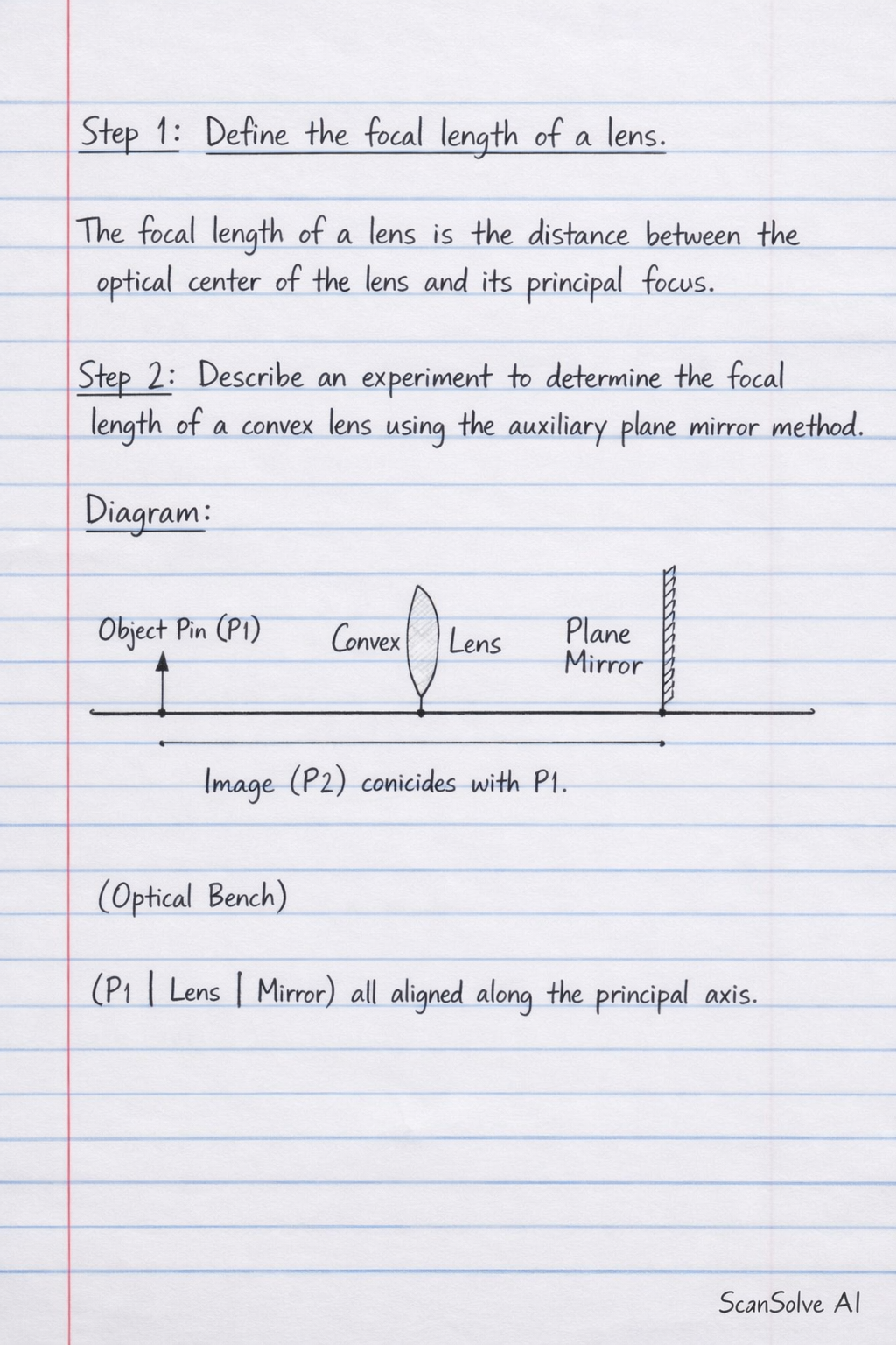
Step 1: Define the focal length of a lens. The focal length of a lens is the distance between the optical center of the lens and its principal focus. Step 2: Describe an experiment to determine the focal length of a convex lens using the auxiliary plane mirror method. Diagram: Object Pin (P1) Convex Lens Plane Mirror Image (P2) coincides with P1 (Imagine a straight line representing the optical bench. P1 is on the left, then the lens, then the mirror on the right, all aligned along the principal axis.) Procedure: 1. Place the convex lens on a lens holder on an optical bench. 2. Place a plane mirror vertically behind the convex lens, ensuring its reflecting surface is perpendicular to the principal axis of the lens. 3. Place an object pin (P1) in front of the convex lens. 4. Adjust the position of the object pin until its inverted image (P2), formed by the lens-mirror combination, coincides with the object pin itself. 5. Measure the distance between the optical center of the convex lens and the object pin. This distance is the focal length (f) of the convex lens. How data collected will be used to arrive at a conclusion: When the image formed by the lens-mirror combination coincides with the object pin, it means that the light rays from the object, after passing through the lens, strike the plane mirror normally (at 90 degrees). For this to happen, the rays must be parallel to the principal axis when they reach the mirror. For a convex lens, rays that become parallel after passing through the lens must have originated from its principal focus. Therefore, the object pin is placed at the principal focus, and the measured distance is the focal length. Precautions taken to minimize errors: • Ensure the lens, mirror, and object pin are vertically upright and aligned along the principal axis to avoid tilted images. • Avoid parallax error when measuring the distance between the lens and the object pin by viewing perpendicular to the scale. • Use a brightly lit object pin to clearly observe the coincidence of the object and its image. • Repeat the measurement several times and calculate the average to improve accuracy. Step 3: Complete the diagram and explain the path of water from hole A. Diagram Completion: Hole A is at the top of the water column. The pressure at hole A will be the lowest. Therefore, the water jet from hole A will have the shortest horizontal range and will fall closest to the bottle, similar to a short arc. (Imagine a short, curved line originating from hole A and falling to the left of the existing path from B, landing closer to the bottle.) Explanation: Pressure in a liquid increases with depth. Hole A is at the shallowest depth compared to holes B and C. Consequently, the water pressure at hole A is the lowest, resulting in the least force pushing the water out and thus the shortest horizontal range for the water jet. Step 4: Calculate the pressure of water at hole C and compare it with the pressure at hole B. Given: Density of water = 1000 kg m^-3. Assume acceleration due to gravity g = 10 m s^-2. Depth of hole C (h_C): Hole C is at the bottom of the water column. h_C = 15 cm = 0.15 m Pressure at hole C (P_C): P_C = g h_C P_C = (1000 kg m^-3) × (10 m s^-2) × (0.15 m) P_C = 1500 Pa Depth of hole B (h_B): Hole B is 7 cm from the bottom. h_B = 15 cm - 7 cm = 8 cm = 0.08 m Pressure at hole B (P_B): P_B = g h_B P_B = (1000 kg m^-3) × (10 m s^-2) × (0.08 m) P_B = 800 Pa Comparison: The pressure at hole C is 1500 Pa, and the pressure at hole B is 800 Pa. Therefore, the pressure at hole C is greater than the pressure at hole B. The pressure at hole C is 1500 Pa and the pressure at hole B is 800 Pa. The pressure at hole C is greater than the pressure at hole B. Step 5: State two properties of pressure in liquids demonstrated in the experiment. 1. Pressure in a liquid increases with depth. (Evidenced by the different ranges of water jets from holes at different depths). 2. Liquids exert pressure on the walls of their container. (Evidenced by the water being forced out of the holes). Step 6: Name the phenomenon responsible for image formation in a plane mirror. The phenomenon responsible for image formation in a plane mirror is reflection. Step 7: Explain what is meant by "laterally inverted image" and give one example of its application in everyday life. A laterally inverted image is an image where the left and right sides of the object appear to be interchanged. For example, if you raise your right hand, your image in a plane mirror appears to raise its left hand. An everyday application is the word "AMBULANCE" written in reverse on the front of an ambulance. This allows drivers of vehicles in front to read the word correctly in their rearview mirrors, making it easily identifiable. Step 8: State 2 other characteristics of the image formed by a plane mirror. 1. The image is virtual (it cannot be formed on a screen). 2. The image is upright (erect) relative to the object. 3. The image is the same size as the object. 4. The image is formed at the same distance behind the mirror as the object is in front.